
With Visual Paradigm Online you dont need to start each PID from scratch because a rich set of piping. PID separator vessel example.

What Is A Piping And Instrumentation Diagram P Id Edrawmax In 2022 Piping And Instrumentation Diagram Diagram P Id Diagram
Check out our template for a PID of 3-phase separator vessels.

. It is a very important industrial diagram representing the exact working of the processes in an industrial plant. A piping and instrumentation diagram PID is a graphic representation of a process system that includes the piping vessels control valves instrumentation and other process components and equipment in the system. They vary in complexity and can take many different forms ranging from hand drawn to software drawn.
Piping and Instrumentation Diagram PID or Process Engineering Flow Scheme PEFS is a detailed drawing that consists of control devices piping process equipment and instrumentation in the form of a diagram. Piping and instrumentation diagrams PIDs show how industrial process equipment is interconnected by a system of pipelines. The shapes in this legend are representative of the functional relationship between piping instrumentation and system equipment units.
At the design stage the diagram also provides the basis for the development of system control schemes like Hazard and Operability Study HAZOP. Process equipment such as valves instruments and pipelines are identified by codes and symbols. Remember to familiarize yourself with abbreviations component codes and diagram basics before you start.
The main components are PID symbols representing pumps motors pumps compressors and towers. The PID diagram software comes with a rich set of high-quality PID symbols for you to create different kinds of PID diagrams. PID drawings help industry professionals easily design.
It is an essential part of the development process as it involves detailed engineering. Without a doubt Visual Paradigm Online is the best PID software to create schematics for the process industry. To draw a PID there are 8 simple steps to help depict the process involving the inputs outputs and components of the system.
Weve broken them down into seven main groups. You can use it from any device or location without worry about. As you modify diagrams you can easily generate new lists.
As well as devices and pipelines a PID will commonly contain information on vents drains and sampling lines as well as flow. For processing facilities its a graphic representation of. There are usually mostly made and used by engineers designing a manufacturing process for a particular.
These components are used in the oil and gas industry to separate various liquids that flow from oil wells. Function and purpose of PIDs. Lucidchart is fast friendly and completely cloud-based.
Piping Instrumentation Diagram PID is a graphical and schematic representation of the functional relationship between piping instrumentation and system equipment components used in the field of automation and instrumentation. Posted on December 21 2017 by Jeff_Rinker. PID schematics also show the instruments and valves that monitor and control the flow of materials through the pipelines.
Safety of system design. Piping and instrumentation diagrams or PIDs are used to create important documentation for process industry facilities. The symbols contained in PIDs represent the equipment in the process such as actuators sensors and controllers.
It uses specific PID symbols to visually show the processes the equipment and their connection and relationship with each other. PIDS are foundational to the maintenance and modification of the process that it graphically represents. One of the priorities during the development process is the implementation of safety features.
The PID is the primary schematic drawing used for laying out a process control. This type of technical drawing is commonly used in practical fields such as engineering and process industry. PID diagrams depict the connection between piping equipment vessels and process components.
Many hidden hazards affect the proper. Try out this template.

What Is Piping And Instrumentation Diagram P Id Piping And Instrumentation Diagram Mechanical Engineering Design Hvac Design

Draw P Id Diagrams Online In The Browser With Google Docs P Id Diagram Diagram Online Drawing

Flowchart Maker How To Read Piping And Instrumentation Diagram Piping And Instrumentation Diagram Diagram Process Flow Diagram

Piping And Instrumentation Diagram P Id Software Piping And Instrumentation Diagram P Id Diagram Id Software

P Id Flow System Example P Id Diagram Piping And Instrumentation Diagram Example

Factory Pid In 2022 Piping And Instrumentation Diagram Diagram Mind Mapping Tools

Coriolis Piping And Instrumentation Diagram P Id Diagram Diagram
プロセス Pid Piping And Instrumentation Diagram Diagram Process Flow Diagram
How To Read Piping And Instrumentation Diagram P Id Piping And Instrumentation Diagram P Id Diagram Diagram

What Is A P Id Diagram In Laymen S Term Realpars P Id Diagram Diagram Piping And Instrumentation Diagram

Piping And Instrumentation Diagram P Id Piping And Instrumentation Diagram P Id Diagram Chemical Engineering

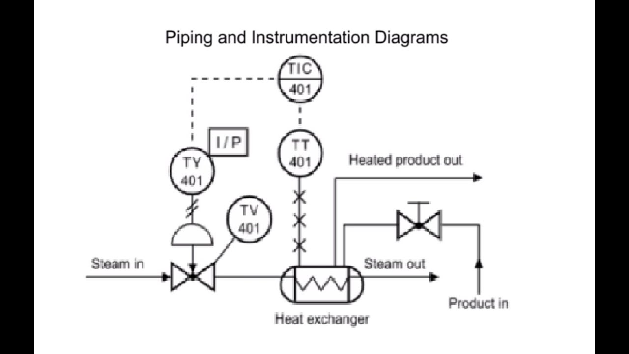
P Id Guidelines For Pumps Heat Exchangers Heat Exchanger P Id Diagram Heat

Plc Control System Control Systems Engineering Control Engineering Process Control

Water Boiling Process Pid Free Water Boiling Process Pid Templates In 2022 Piping And Instrumentation Diagram P Id Diagram Software Project Management

How To Read Piping And Instrumentation Diagram P Id Piping And Instrumentation Diagram P Id Diagram Diagram

P Id Flow System Example P Id Diagram Piping And Instrumentation Diagram Example

P Id Guidelines For Pumps Heat Exchangers Heat Exchanger P Id Diagram Heat

P Id Guidelines For Centrifugal Compressor Systems Centrifugal Compressor Compressor P Id Diagram

A Process Flow Diagram Shows The Relationships Between The Major Equipment S Columns Ves Process Flow Diagram Process Flow Piping And Instrumentation Diagram


